
Olympus FL-40 flash lower housing repair
By Dr. Gonzo
This is a specialized article that covers how to disassemble and reassemble the lower housing of the FL-40 flash.
This area is prone to damage from drops and bangs, and is fairly easily repairable using parts available
from the Olympus parts department.
FL-40 lower housing assembly parts list
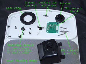
Though we haven't disassembled the thing yet, I thought the parts list was a good thing to start with, as it's probably
the most important reference image in this article. Click the image above to enlarge. Note that the names I use are arbitrary, i.e. they
are not "official" Olympus names for these parts. The parts in the lower housing assembly are:
- The lower housing shell: Asquare-ish plastic unit that makes up the bottom part of the FL-40, from just above the
hotshoe to just below the power switch. Olympus part number VC122900.
- Hotshoe: The plastic piece that fits to your camera. It is threaded on the outside for the locking ring, and 5 holes are drilled through it --
4 for the TTL contacts and one for the locking pin.
- Lock ring: Large knurled ring that rides on the outside of the hotshoe. It has a ramp on one surface that actuates the locking pin.
- TTL contact board: the circuit board inside the lower housing that connects the TTL contacts to the flash processor. It has 4 springs
which sit behind the TTL contact pins themselves.
- TTL contact pins: These four pins extend through the hotshoe and connect the flash to the camera's TTL contacts.
- Ground contact: This piece of spring metal sits in the hotshoe and is soldered to the TTL contact board.
- Locking pin and screw: This pin sits in the hotshoe and has a tang which is actuated by the ramp on the locking ring. The spring applies
tension so that the pin's resting state is fully retracted within the hotshoe.
- Retaining screws: The lower housing assembly has 12 screws: four external screws that hold the whole thing onto the flash,
four flat-headed screws that hold the TTL contact board down and four screws that hold the hotshoe onto the lower housing shell.
Tools needed
- Precision screwdrivers (phillips head)
- Soldering iron
- Desoldering tool (not absolutely necessary)
The problem
Here's what was wrong with my flash:
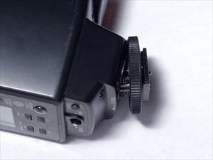
Clearly, the damn thing was broken. Upon disassembly I found it was my lower housing shell that had cracked, allowing the
hotshoe to pull away from it. Other problems might include chipped hotshoes or damaged lock rings.
Disassembly
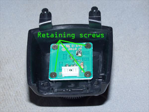
STEP 1: Remove the external screws
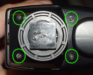
First take off the external screws. There are only four as shown above.
STEP 2: Separate the lower housing assembly
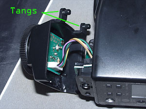
Remove the lower housing by pulling down the side nearest the power switch, then removing at an angle so as to get the
two tangs seen above clear of the housing. Carefully remove the connector.
STEP 3: Remove TTL board screws
The four TTL board screws are at each corner of the board. These screws have flat heads and require a smaller
screwdriver than the external screws.
STEP 4: Desolder the ground
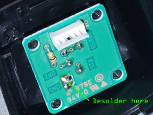
This is about the only remotely difficult part of this process. Fire up the soldering gun and desolder the
connection marked "GND" on the board. This is the ground strap, and holds the TTL board onto the assembly even
if the screws are taken out. Since you already removed the board's retaining screws, it will be under pressure from the springs
beneath it. You may use the desoldering tool here or not -- the board will probably "pop up" once the solder is melted due to the
spring pressure.
Set aside the TTL board and turn the assembly upside-down to dislodge the four TTL contact pins. Don't worry about remembering
which direction they were sitting in, they can only go in one way.
STEP 5: Remove the hotshoe screws
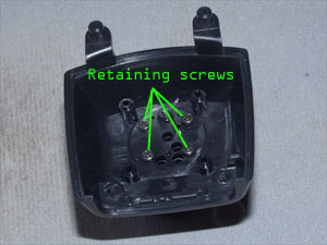
The hotshoe assembly is held onto the lower housing shell by four screws as shown above. These should be identical to the external screws.
STEP 6: The hotshoe assembly
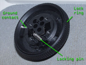
This is the last part of the lower housing assembly. The hotshoe assembly consists of the lock ring, which rides
around the outside of the hotshoe, the locking pin and spring and the ground contact.
It's pretty self-explanatory at this point but here are the salient points:
- The locking pin goes large-side down. If you put it in upside down, the spring won't fit.
- The ground contact sits in a U-shaped groove in the hotshoe. Easy to understand once you see it.
- Prior to assembly, the lock ring must be adjusted so that the ramp on its concave face properly actuates the
locking pin's tang. The best way to figure this part out is to put the ring on the shoe and lock it on your camera's hotshoe socket, then
insert the pin. That way you are assured that the ring is on the proper part of the threads of the hotshoe.
Re-Assembly
Re-assembly of the lower housing is a simple reversal of the steps EXCEPT one:
Screw the TTL contact board down before you re-solder the ground contact. You probably won't
need to add any solder; there should be enough there from the factory bead (and any you used to tin the soldering iron's tip)
to be solid.
That's it! As usual, I take no responsibility for anything that happens to you or your flash if you follow my directions, so DO
THIS AT YOUR OWN RISK! If you have any further questions, email me.
Contacting Olympus USA parts department
Olympus USA's parts department number is 1-800-622-6372. The extension number is 1620. For smaller parts, Olympus USA
ships from New York via US postal with no upfront payment, then requests reimbursement for shipping charges (usually $5).
|


